SAGA System for Helicopter Takeoff, Approach and Landing area Approach A...
Product Description
Airfield airport SAGA System for Helicopter Takeoff, Approach and Landing area Approach Azimuth Guidance.
Location on the field
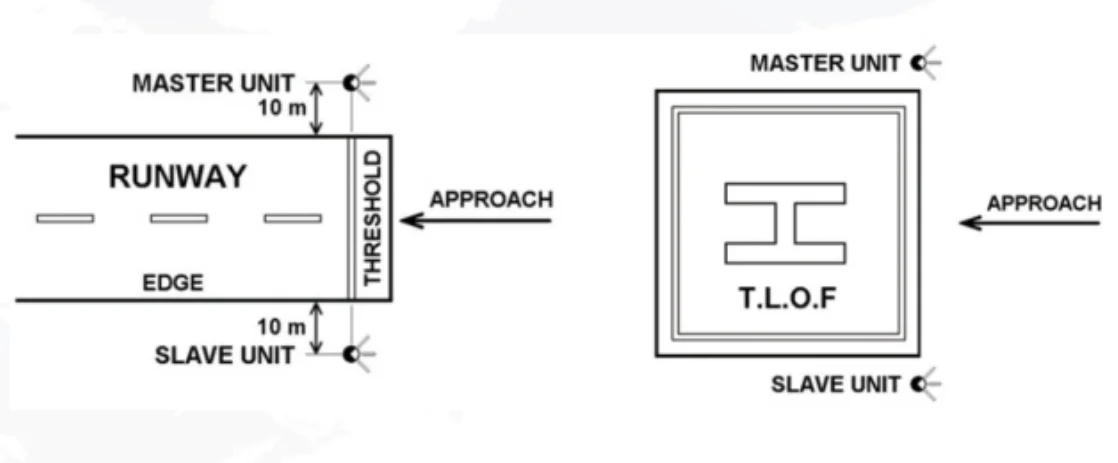
The two light units of a SAGA system installed at 10 metres from the runway Edge symmetrically on both sides of the Runway threshold (for TLOF the two units installed as close as possible to the threshold edges).
The Master unit installed on the right of the Threshold and the Slave unit on the left.
How Works
The SAGA system includes two light units (one Master and one Slave) placed symmetrically on both sides of the Runway (or TLOF) threshold supplying unidirectional rotating beams which give a flashing effect. The pilot receives, each second illumination of two “Flashes” provided in sequence with the two light units.
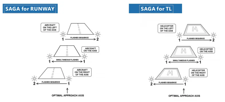
When the aircraft flies inside a 9° width angular sector, cen tred on the approach axis, the pilot sees the two lights “flashing” simultaneously.
When the aircraft flies inside a 30° width angular sector, centred on the approach axis and outside the previous one, the pilot sees the two lights“flashing” with a variable delay (60 to 330 ms) according to the position of the aircraft in the sector. The further the aircraft is from the axis, the greater the delay. The delay between the two“flashes”produces a sequence effect which shows the direction of theaxis
When the aircraft flies inside a 30° width angular sector, centred on the approach axis and outside the previous one, the pilot sees the two lights“flashing” with a variable delay (60 to 330 ms) according to the position of the aircraft in the sector. The further the aircraft is from the axis, the greater the delay. The delay between the two“flashes”produces a sequence effect which shows the direction of theaxis
The visual signal is not visible when the aircraft flies outside the 30° angularsector.
For more details , Please feel free to Contact :
emma@chendongtech.com
what'sapp :0086-13342512879
Skype: chendongtech1
Product Presentation
Specification
* The System of Azimuth Guidance for Approach will comply with ICAO recommendations Annex 14, Volume I paragraph 5.3.4 and French STAC.
* It will comprise of 2 “Flashing” Units (master and slave) located symmetrically on both sides of the runway (or TLOF for heliport) threshold
* Depending of his position on the approach axis, the pilot will receive visual information of two “Flashes” supplied by the two “flashing” units of the SAGA.
* If the pilot is on the axis +/-0.45°, the two “Flashes”are simultaneous.
* If the pilot is not on the axis within an angle comprise between -30 and +30°, The two “Flashes”will be see delayed of a time between 60 and 330 ms (the further the aircraft is from the axis, the greater the delay). The delay between the two“flashes” produces a sequence effect which shows the direction of the axis.
* The SAGA system will be powered in 110Vac-230Vac 50/60 Hz. It will be equipped with 12 Vac 105 W pre-focused reflector lamps.
* It will be remotely controlled in 48Vdc.
* Monitoring will be possible through 2 dedicated dry contacts.
* The SAGA system will be available with heating resistors for cold and/or wet areas.
* The system will be automatically put out of service if at least one of its two “Flashing” Units becomes defective.
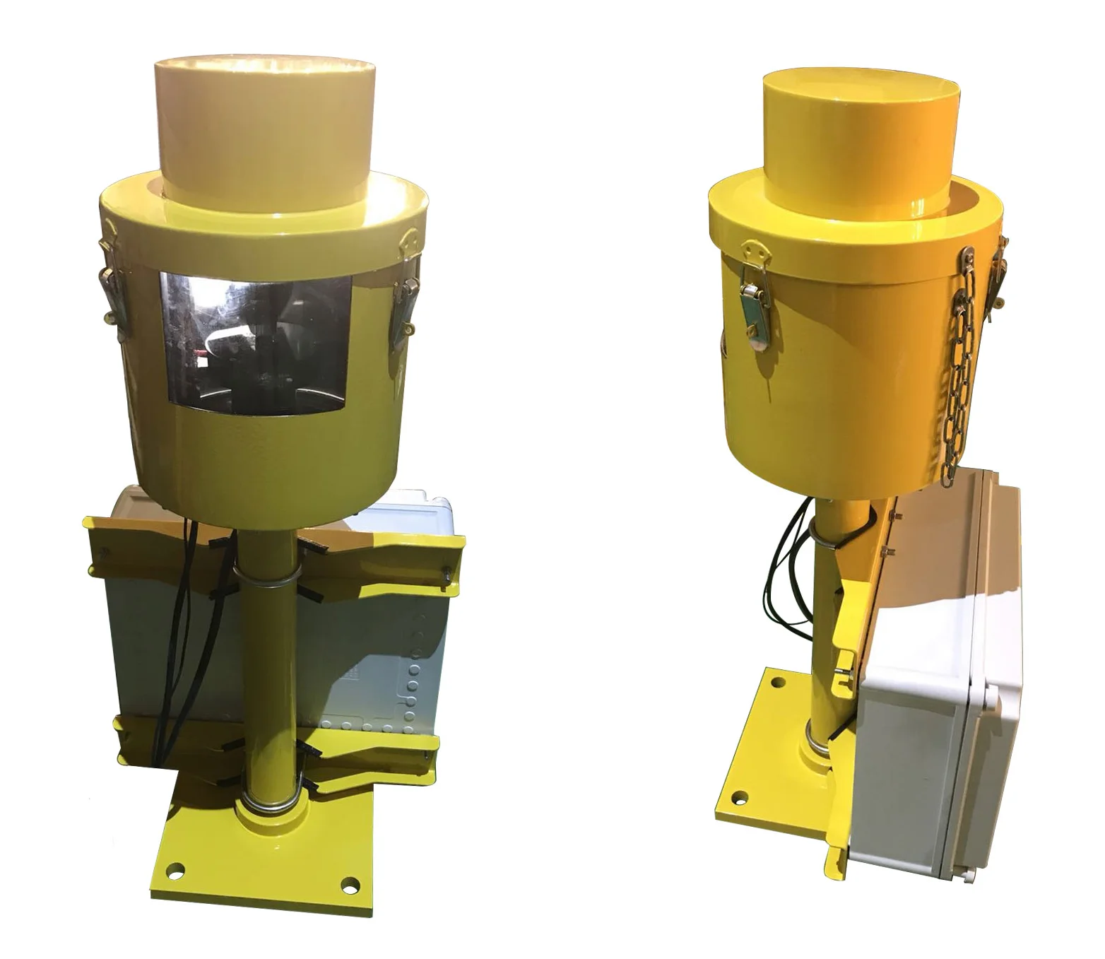
* The Body, Cap and Support of the “Flashing” Unit will be in aluminium alloy, phosphate and painted in aviation yellow. All fixings and fastenings will be stainless steel. The Power Supply Box will be made of reinforced polyester and will be IP 65 rated.
* The legs of the “Flashing Units” will be frangible.


Comments